STP
STP
Протокол STP (Spanning Tree Protocol) - это протокол второго уровня, выполняемый на мостах и коммутаторах. Спецификация для STP называется IEEE 802.1D. Основная цель STP - предотвращение создания петель при наличии в сети избыточных путей.
Рассмотрим сеть:

В этой сети планируется создание резервного канала между коммутатором А и коммутатором В. Однако в данной конфигурации возможно возникновение замкнутой петли. К примеру, широковещательная или многоадресная рассылка, которая передается со станции A на станцию B, будет просто циркулировать между двумя коммутаторами.
К примеру, PC A хочет поговорить с PC B.
1) PC A отправляет broadcast запрос ARP
2) коммутатор A получает этот фрэйм и рассылает его на все порты кроме порта, с которого он получил это фрэйм (f0/5).
3) Предположим, SW3 получил broadcast сперва на порт f0/0 (на f0/1 он придет позже)

4)SW3 рассылает broadcast на все порты, кроме того, на который пришел этот broadcast. (Т.е. широковещательное сообщение посылается на f0/5 и f0/1)
5) на f0/1 SW3 приходит broadcast

6)SW3 рассылает broadcast на все порты, кроме того, на который пришел этот broadcast. (Т.е. широковещательное сообщение посылается на f0/5 и f0/0)
Как мы видим SWA послал 2 broadcast'а: на f0/0 и на f0/1. SWB сделал из них 4 broadcast, 2br отправил на PCB, 2br отправил обратно на SWA. Когда SWA получает 2br, он делает из них 4br и 2 из них отправляет на SWB и так продолжается бесконечно, пока не упадет сеть, или отключится один из интерфейсов. Это есть broadcast storm. Он снижает пропускную способность сети и создает проблемы протоколам, так как они ожидют получить одну копию файла, а не две.
STP решает проблемы со штормом, путем блокирования одного из интерфейсов.
1. Elects one root bridge
2. Select one root port per nonroot bridge
3. Select one designated port on each network segment
1. Выбор root bridge
A fun thing is that when turned on, each switch claims itself as the root bridge immediately and starts sending out multicast frames called Bridge Protocol Data Units (BPDUs), which are used to exchange STP information between switches.
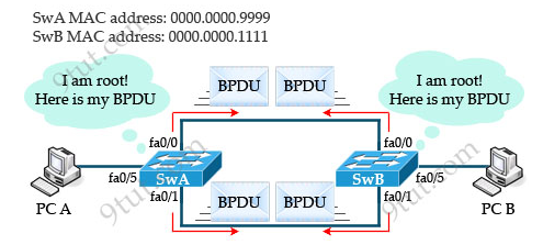
+ The bridge priority of SwA is 32768 and its MAC address is 0000.0000.9999 -> the bridge ID of SwA is 32768:0000.0000.9999
+ The bridge priority of SwB is 32768 and its MAC address is 0000.0000.1111 -> the bridge ID of SwB is 32768:0000.0000.1111
To compare two bridge IDs, the priority is compared first. If two bridges have equal priority, then the MAC addresses are compared. In the above example, both SwA and SwB have the same bridge ID (32768) so they will compare their MAC addresses. Because SwB has lower MAC address it will become root bridge.


Every non-root bridge must have a root port. All root ports are placed in forwarding state.
In the above example, if we suppose the upper link (between two fa0/0 interfaces) are 10Mbps and the lower link (between two fa0/1 interfaces) is 100Mbps link then fa0/1 of SwA will become root port as it has lower cost than fa0/0 (cost 19 < cost 100).
 3. Выбор designated port on each network segment
STP selects one designated port per segment to forward traffic. Other switch ports on the segment typically become nondesignated ports and are blocked. Therefore interface fa0/0 of SwA will become nondesignated port (blocking state). In blocking state, although switches cannot send data traffic but can still receive BPDUs. У root bridge все порты designated
 When the lower link is broken, SwA must wait for Max Age seconds before
it begins to transition fa0/0 interface from blocking to listening
state. In listening state it must wait for the Forward Delay seconds (15) to
move to the Learning state. Next it continues waiting for more Forward
Delay seconds (15). If no BPDU is received, it is then placed in forwarding
state. These three waiting periods of (by default) 20, 15, and 15
seconds create STP’s relatively slow convergence.
When the lower link is broken, SwA must wait for Max Age seconds before
it begins to transition fa0/0 interface from blocking to listening
state. In listening state it must wait for the Forward Delay seconds (15) to
move to the Learning state. Next it continues waiting for more Forward
Delay seconds (15). If no BPDU is received, it is then placed in forwarding
state. These three waiting periods of (by default) 20, 15, and 15
seconds create STP’s relatively slow convergence.

Per VLAN Spanning Tree (PVST) maintains a spanning tree instance for each VLAN configured in the network. It means a switch can be the root bridge of a VLAN while another switch can be the root bridge of other VLANs in a common topology. For example, Switch 1 can be the root bridge for Voice data while Switch 2 can be the root bridge for Video data. If designed correctly, it can optimize the network traffic.
(по умолчанию включен STP. Есть ещё pvst и rapid-pvst=rstp с vlans)
Enabling PVST
en
∟conf t
∟spanning-tree vlan 10,11,12
Root Switch Selection
en
∟conf t
∟spanning-tree vlan 10 root primary (Set the switch to become the root switch.)
∟spanning-tree vlan 20 root secondary (Set the switch to become the root switch.)
http://www.9tut.com/rapid-spanning-tree-protocol-rstp-tutorial
https://habrahabr.ru/post/170895/
https://habrahabr.ru/post/89997/
Протокол STP (Spanning Tree Protocol) - это протокол второго уровня, выполняемый на мостах и коммутаторах. Спецификация для STP называется IEEE 802.1D. Основная цель STP - предотвращение создания петель при наличии в сети избыточных путей.
Рассмотрим сеть:
В этой сети планируется создание резервного канала между коммутатором А и коммутатором В. Однако в данной конфигурации возможно возникновение замкнутой петли. К примеру, широковещательная или многоадресная рассылка, которая передается со станции A на станцию B, будет просто циркулировать между двумя коммутаторами.
К примеру, PC A хочет поговорить с PC B.
1) PC A отправляет broadcast запрос ARP
2) коммутатор A получает этот фрэйм и рассылает его на все порты кроме порта, с которого он получил это фрэйм (f0/5).
3) Предположим, SW3 получил broadcast сперва на порт f0/0 (на f0/1 он придет позже)
4)SW3 рассылает broadcast на все порты, кроме того, на который пришел этот broadcast. (Т.е. широковещательное сообщение посылается на f0/5 и f0/1)
5) на f0/1 SW3 приходит broadcast
6)SW3 рассылает broadcast на все порты, кроме того, на который пришел этот broadcast. (Т.е. широковещательное сообщение посылается на f0/5 и f0/0)
Как мы видим SWA послал 2 broadcast'а: на f0/0 и на f0/1. SWB сделал из них 4 broadcast, 2br отправил на PCB, 2br отправил обратно на SWA. Когда SWA получает 2br, он делает из них 4br и 2 из них отправляет на SWB и так продолжается бесконечно, пока не упадет сеть, или отключится один из интерфейсов. Это есть broadcast storm. Он снижает пропускную способность сети и создает проблемы протоколам, так как они ожидют получить одну копию файла, а не две.
STP решает проблемы со штормом, путем блокирования одного из интерфейсов.
How Spanning Tree Protocol (STP) works
SPT must performs three steps to provide a loop-free network topology:1. Elects one root bridge
2. Select one root port per nonroot bridge
3. Select one designated port on each network segment
1. Выбор root bridge
A fun thing is that when turned on, each switch claims itself as the root bridge immediately and starts sending out multicast frames called Bridge Protocol Data Units (BPDUs), which are used to exchange STP information between switches.
• The Bridge IDs of the Root Bridge and the Bridge ID of the Transmitting Bridge
Bridge ID = Bridge Priority + MAC Address (The root bridge is the bridge with the lowest bridge ID.)
For example:+ The bridge priority of SwA is 32768 and its MAC address is 0000.0000.9999 -> the bridge ID of SwA is 32768:0000.0000.9999
+ The bridge priority of SwB is 32768 and its MAC address is 0000.0000.1111 -> the bridge ID of SwB is 32768:0000.0000.1111
To compare two bridge IDs, the priority is compared first. If two bridges have equal priority, then the MAC addresses are compared. In the above example, both SwA and SwB have the same bridge ID (32768) so they will compare their MAC addresses. Because SwB has lower MAC address it will become root bridge.
• The cost to reach the root from this bridge (Root Path Cost):
This value is set to 0 at the beginning of STP root bridge election
process since all bridges claim to be the root. The cost range is
0-65535.
• The Port ID:
The transmitting switch port ID
2. Выбор root порта на nonroot bridge
Root port is the port that is closest to the root bridge, which means it is the port that receiving the lowest-cost BPDU from the root.Every non-root bridge must have a root port. All root ports are placed in forwarding state.
In the above example, if we suppose the upper link (between two fa0/0 interfaces) are 10Mbps and the lower link (between two fa0/1 interfaces) is 100Mbps link then fa0/1 of SwA will become root port as it has lower cost than fa0/0 (cost 19 < cost 100).
STP selects one designated port per segment to forward traffic. Other switch ports on the segment typically become nondesignated ports and are blocked. Therefore interface fa0/0 of SwA will become nondesignated port (blocking state). In blocking state, although switches cannot send data traffic but can still receive BPDUs. У root bridge все порты designated
* Blocking – no user data is sent or received but it may go into
forwarding mode if the other links in use fail and the spanning tree
algorithm determines the port may transition to the forwarding state.
BPDU data is still received in blocking state but discards frames, does
not learn MAC address.
* Listening – The switch processes BPDUs and awaits possible new
information that would cause it to return to the blocking state,
discards frames and MAC address.
* Learning – receives and transmits BPDUs and learns MAC addresses but does not yet forward frames.
* Forwarding – receives and sends data, normal operation, learns MAC address, receives and transmits BPDUs.
* MaxAge – How long any bridge should wait, after
beginning to not hear hellos, before trying to change the STP topology.
Usually this is a multiple of the hello time; the default is 20 seconds.
* Forward Delay – Delay that affects the time
involved when an interface changes from blocking state to forwarding
state. A port stays in listening state and then learning state for the
number of seconds defined by the forward delay. This timer is covered in
more depth shortly
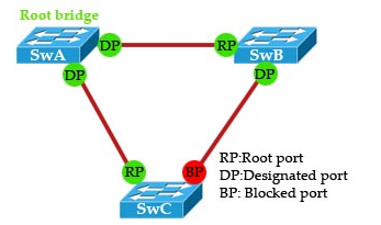
Работа на примере:
In which SwA is elected the root bridge, the link between SwB and SwC
is being blocked. When STP is converged, the port roles are shown
above.
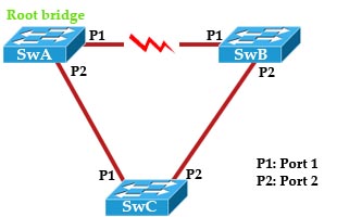
Now suppose the link between SwA and SwB goes down, let us see what and how STP will perform
1. First, P1 on SwB immediately goes down and SwB declares its link to SwA as down.
2. SwB considers its link to SwC (which is being blocked) as an alternate link to root port. SwB starts to transition P2 from the blocking state to listening state -> learning state -> forwarding state. Each of these stages lasts 15 seconds by default. Therefore port P2 on SwB will be hold blocking for 30 seconds before the network converges again. This downtime of the network is rather long (although we can tune the timers to 14 second downtime) and the users can feel it.
2. SwB considers its link to SwC (which is being blocked) as an alternate link to root port. SwB starts to transition P2 from the blocking state to listening state -> learning state -> forwarding state. Each of these stages lasts 15 seconds by default. Therefore port P2 on SwB will be hold blocking for 30 seconds before the network converges again. This downtime of the network is rather long (although we can tune the timers to 14 second downtime) and the users can feel it.
set spantree priority 8192 1 (Приоритет по умолчанию для коммутаторов равен 32768)
set spantree root 1,200-204
set spantree portfast 3/1-24 enable
Per VLAN Spanning Tree (PVST) maintains a spanning tree instance for each VLAN configured in the network. It means a switch can be the root bridge of a VLAN while another switch can be the root bridge of other VLANs in a common topology. For example, Switch 1 can be the root bridge for Voice data while Switch 2 can be the root bridge for Video data. If designed correctly, it can optimize the network traffic.
(по умолчанию включен STP. Есть ещё pvst и rapid-pvst=rstp с vlans)
Enabling PVST
en
∟conf t
∟spanning-tree vlan 10,11,12
Root Switch Selection
en
∟conf t
∟spanning-tree vlan 10 root primary (Set the switch to become the root switch.)
∟spanning-tree vlan 20 root secondary (Set the switch to become the root switch.)
-
vlan_id show spantree
— Показывает текущее состояние связующего дерева для этого
ИДЕНТИФИКАТОРА VLAN, с точки зрения коммутатора, на котором вы
выполняете команду.
-
show spantree summary
Предоставляет сводку подключенных сетью VLAN портов связующего дерева.
-
show spantree statistics
Отображает статистические сведения о связующем дереве.
-
show spantree backbonefast
— Отображает, включена ли функция связующего дерева Backbone Fast Convergence.
-
show spantree blockedports
только блокированные порты.
-
show spantree portstate
— Определяет текущее состояние связующего дерева Порта Token Ring в связующем дереве.
-
show spantree portvlancost
— Показывает стоимость пути для сетей VLAN на порте.
-
show spantree uplinkfast
— Отображает настройки uplinkfast.
http://www.9tut.com/rapid-spanning-tree-protocol-rstp-tutorial
https://habrahabr.ru/post/170895/
https://habrahabr.ru/post/89997/

Comments
Post a Comment